NONchuk joystick interface
MyRetroMax MyRetroMax-docs CircuitGizmos 37Sensors
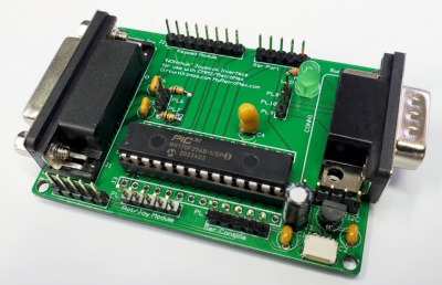
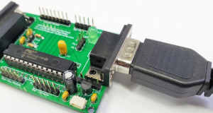
The NONchuk board provides a way to interface joysticks and other devices to the RetroMax. The intention is to use the I2C port on the NONchuk to connect to the Nunchuk interface on the RetroMax (or CMM2).
The NONchuk allows the Nunchuk port of the RetroMax to connect to joysticks and several other devices. Since there are a variety of different devices that can be connected, the NONchuk uses a MicroMite chip (the '170 with MMBasic installed) to run code for the task.
The NONchuck has a console port that can be used as the serial interface for programming the MMBasic code specific to how the NONchuk will be used.
The NONchuk features:
• Based on MMBasic '170 so it can be user re/programmed
• Support Atari (digital/switch) joystick
• Support PC (analog/potentiometer) joystick
• Operate as I2C slave interface
• Operate as serial interface
• Support 16 key keypad
• Support rotary module
• Support analog joystick module
The NONchuck board could also be used as a stand-alone MicroMite ('170 chip) board. For example it could be used with a joystick and various pins from the microcontroller could control relays, LEDs, etc.
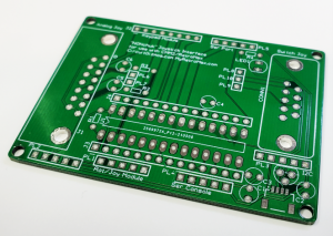
Buy the NONchuk PCB here:
https://circuitgizmos.com/NONchuk-PCB-p363024751
Or make the PCB yourself:
| Linked file: NONchuk1a.zip |
The NONchuk has an on-board 3.3V regulator if the source power for the board is 5V. The board will work from either 5V or 3.3V. The MicroMite on the board runs at 3.3V. If 3.3V is present to the board the power LED will illuminate. Power and ground connections can be found on several of the connection points.
On either side of the NONchuk microcontroller (MicroMite) are a row of connections that connect one to one to the 28 pins of the MicroMite. These provide simple/easy access to all of the MicroMite pins.
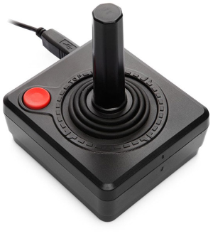
Atari Joystick Connection
The NONchuk has a 9-pin male connector that can be used to interface to an "Atari" style of joystick. This type of joystick has been called "digital" to make the distinction that it is not an analog joystick. Operating the stick left, right, up, or down presses against a switch. The switch makes a connection between a designated pin on the joystick connector and the ground pin. The same thing applies to the joystick trigger/fire button.
In the NONchuck schematic, the five pins for up, down, right, left and fire are shown connected to the MicroMite pins P23, P24, P25, P26, and P16 respectively. Turning on an internal MicroMite pullup resistor when these pins are set to input makes the unpressed state of the joystick switches to be a logic high (1), and the pressed state a logic low (0).
A simple program that reads just the inputs for the digital joystick (Atari-style switch inputs) and prints them to the console connection starts by setting up the pins as inputs before making a loop that prints which switch is activated.
SETPIN 16, DIN, PULLUP
SETPIN 23, DIN, PULLUP
SETPIN 24, DIN, PULLUP
SETPIN 25, DIN, PULLUP
SETPIN 26, DIN, PULLUP
DO
PAUSE 50
IF PIN(16) = 0 THEN PRINT "Fire"
IF PIN(23) = 0 THEN PRINT "Up"
IF PIN(24) = 0 THEN PRINT "Down"
IF PIN(25) = 0 THEN PRINT "Left"
IF PIN(26) = 0 THEN PRINT "Right"
LOOP
SETPIN 23, DIN, PULLUP
SETPIN 24, DIN, PULLUP
SETPIN 25, DIN, PULLUP
SETPIN 26, DIN, PULLUP
DO
PAUSE 50
IF PIN(16) = 0 THEN PRINT "Fire"
IF PIN(23) = 0 THEN PRINT "Up"
IF PIN(24) = 0 THEN PRINT "Down"
IF PIN(25) = 0 THEN PRINT "Left"
IF PIN(26) = 0 THEN PRINT "Right"
LOOP
Keypad Module Connection
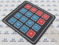
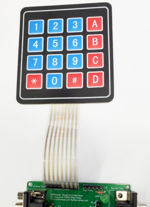
The NONchuk has an 8 pin connector (header pins .1" on center) that can be used for a multiplexed keypad of up to 16 keys (4 row, 4 column). The KEYPAD command built into MMBasic supports either a 4x3 or 4x3 keypad with processing done in the background.
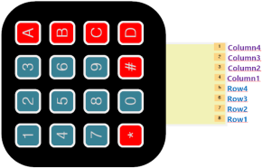
Column and row keys are interchangeable, so this keypad can be plugged in two different ways. The decoding would represent different keys for the alternate orientation, so that will need to be considered in the program. Row pins are P9, P10, P14, and P15. Column pins are P26, P25, P24, and P23.
Below is a simple program that reads the keypad and prints a unique identifier for each of the 16 keys of this keypad copied from the MMBasic user manual. The keypad command lists the NONchuk pins used for the keypad.
Keypad KeyCode, KP_Int, 9, 10, 14, 15, 26, 25, 24, 23
DO
LOOP
KP_Int: ' a key press has been detected
PRINT "Key press = " KeyCode
IRETURN
DO
LOOP
KP_Int: ' a key press has been detected
PRINT "Key press = " KeyCode
IRETURN
Serial Port
The MicroMite has an internal serial UART that connects to the serial port header on the NONchuk. The voltage levels on this port for the transmit (Tx) and receive (Rx) signal lines are 3.3V. Various serial devices can be connected to this serial port. This could allow input to the RetroMax from a serial device that this NONchuk translates into nunchuk codes/movements, or the NONchuk board could be used to translate attached joystick movements to serial data.
A simple program that sends a string to the serial port, pauses, and then receives a string (the same string if this is a loop-back test) is below. P21 is the transmit pin (data out of the NONchuk board) and P22 is the receive pin.
OPEN "COM1:4800" AS #1
PRINT #1, "Hello"
PAUSE 1000
dat$ = INPUT$(20, #1)
PRINT dat$
CLOSE #1
PRINT #1, "Hello"
PAUSE 1000
dat$ = INPUT$(20, #1)
PRINT dat$
CLOSE #1
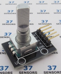
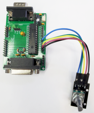
Rotary Encoder / Joystick Module
The NONchuk has a header that can be used to connect to a rotary encoder module or a small joystick module. The header has ground and 3.3V as well as P4, P5, and P6.
The rotary encoder has two output pins that provide a quadrature output of the knob position, as well as a switch output for when the knob is pressed down.
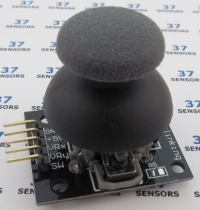
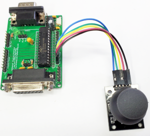
The analog joystick module has a potentiometer that returns a variable voltage for the X position on one pin, and a variable voltage for the Y position on another pin. It also has a switch that is activated when the joystick is pressed down.
The program below sets a starting value of 1000 and then displays the state of the button (on P4) as well as the value variable every 1/5th of a second. The value variable is incremented or decremented when the rotary encoder knob is rotated.
SETPIN 4, DIN, PULLUP
SETPIN 5, DIN, PULLUP
SETPIN 6, INTH, RInt
Value = 1000
DO
PRINT PIN(4) Value
PAUSE 200
LOOP
RInt: ' Interrupt to decode the encoder output
IF PIN(5) = 1 then
Value = Value + 1 ' clockwise rotation
ELSE
Value = Value - 1 ' anti clockwise rotation
ENDIF
IRETURN
SETPIN 5, DIN, PULLUP
SETPIN 6, INTH, RInt
Value = 1000
DO
PRINT PIN(4) Value
PAUSE 200
LOOP
RInt: ' Interrupt to decode the encoder output
IF PIN(5) = 1 then
Value = Value + 1 ' clockwise rotation
ELSE
Value = Value - 1 ' anti clockwise rotation
ENDIF
IRETURN
The small program below will print the analog values of the two potentiometers (multiplied by a constant) and the value returned by the position of the switch.
SETPIN 4, AIN
SETPIN 5, AIN
SETPIN 6, DIN, PULLUP
DO
PRINT INT(PIN(4)*77) INT(PIN(5)*77) PIN(6)
PAUSE 200
LOOP
SETPIN 5, AIN
SETPIN 6, DIN, PULLUP
DO
PRINT INT(PIN(4)*77) INT(PIN(5)*77) PIN(6)
PAUSE 200
LOOP
PC Analog Joystick
The NONchuk has a 15-pin connector for an Analog/PC-style joystick. This type of joystick provides a variable value for the position of the stick control.
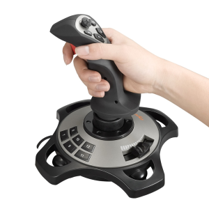
Most of these joysticks follow the general design below with a connection from one side of the potentiometer to 5V, and the wiper to the connector pin. The circuit used on a PC sets up this variable resistor to be part of a circuit that creates a variable length pulse based on the position of the joystick.
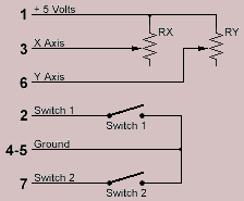
For the NONchuk there is a capacitor connected from the pin to be measured to ground. If the pin is grounded and then released, the line will remain low until the capacitor is charged. That length of time depends on the resistive value of the potentiometer, end thus the joystick position. Measuring that time gives a value that related to the joystick position.
I2C Master
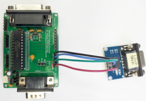
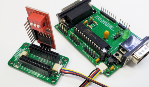
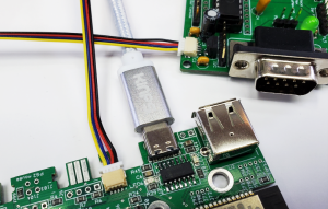
The NONchuk can be an I2C master via the I2C port. This port is present as a 5 pin header with ground, 3.3V, and 5V power connections as well as the SDA (data) and SCL (clock) I2C signal lines. Connections are also made to a small "JST TH" connector of the type used for the I2C bus known as QWIIC. This makes it easy to connect to boards that have this same style QWIIC connector on them. The CircuitGizmos QuickQWIIC board can be used to connect in various ways to many I2C modules, devices, and sensors.
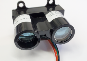
There are a large number of I2C devices that could be connected to the NONchuk. Above is a laser range finder that works via I2C.
The SDA and SCL lines used for I2C are defined as being open collector with approximately 4.7k ohm resistive pull ups. The NONchuck does NOT have these pull up resistors. The resistors would have to be added externally, or be present on the connected I2C module/device for the I2C communication to function reliably.
The code below scans the I2C bus to find the I2C devices that are present. In the picture above a PCF8574A is attached and found at the address of 38H.
' I2C bus scan
' Device address and dummy for data returned
dim devadd as integer
dim dummy as integer
' Open the I2C bus
' 100kHz, .1 sec timeout
I2C OPEN 100,100
' Scan the bus, printing each scanned address
FOR devadd = &H08 TO &H77
PRINT HEX$(devadd)
I2C READ devadd,0,1,dummy
IF MM.I2C = 0 THEN
PRINT "Found device at: ",HEX$(devadd)
ENDIF
NEXT devadd
I2C Slave
The NONchuk can be an I2C slave via the I2C port. This allows the NONchuk to do all of the joystick, keypad, or rotary encoder processing and then communicate with a host (such as a RetroMax) via I2C/Nunchuk connections.
A NONchuk could be programmed to interface to an analog joystick and be connected to a RetroMax via one of the Nunchuk ports. The NONchuk would translate the joystick movements into the communication format used by a Nunchuk. In this way the RetroMax would see an analog joystick as a Nunchuk controller.
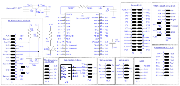
NONchuk Schematic
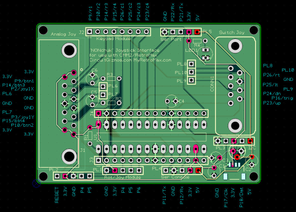
NONchuk board and connector layout
NONchuk Parts List
| Component Name | Value | Description |
|---|---|---|
| C1 | .1 uF | Capacitor |
| C2 | .1 uF | Capacitor |
| C4 | .1 uF | Capacitor |
| C5 | .01 uF | Capacitor |
| C6 | .01 uF | Capacitor |
| C3 | 4.7uF | Capacitor |
| CONN1 | 9pin D M | |
| J1 | PC Joystick female 15 pin 2 row | |
| J2 | 8 pin 1 row | |
| J3 | 14 pin 1 row | |
| J4 | 14 pin 1 row | |
| J5 | JST04_1MM_RA | Qwiic Connector |
| LED1 | Green | LED |
| PL1 | 5 way Pin Header | |
| PL2 | 5 way Pin Header | |
| PL3 | 5 way Pin Header | |
| PL4 | 5 way Pin Header | |
| PL5 | 5 way Pin Header | |
| PL6 | Single Pin Header | |
| PL7 | Single Pin Header | |
| PL8 | Single Pin Header | |
| PL9 | Single Pin Header | |
| PL10 | Single Pin Header | |
| R1 | 10k 1/8W | Resistor |
| R2 | 10k 1/8W | Resistor |
| R3 | 10k 1/8W | Resistor |
| R4 | 330 1/8W | Resistor |
| REG1 | 3.3V | Voltage regulator(TO92) |
| U1 | Micromite | PIC32MX170F256B 28DIP |
All content, not otherwise posted with a copyright notice, is Copyright 2020+ to the owner of MyRetroMax.com.
All of the Color Maximite 2 documentation is copyright of Geoff Graham. It is distributed under a Creative Commons AttributionNonCommercial-ShareAlike 3.0 Australia license (CC BY-NC-SA 3.0)